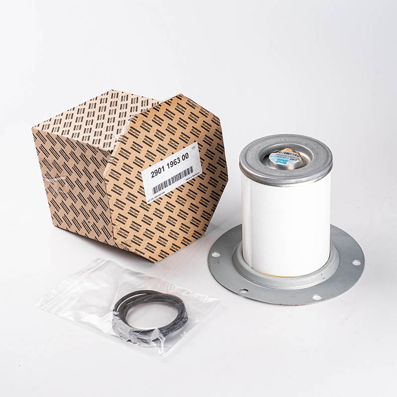
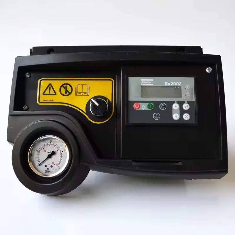
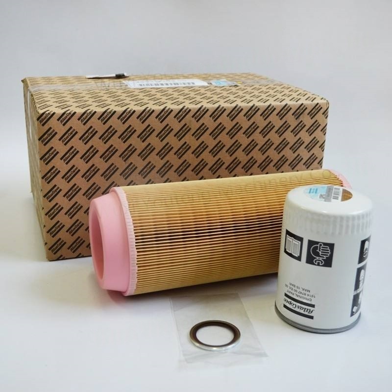
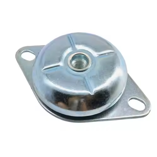
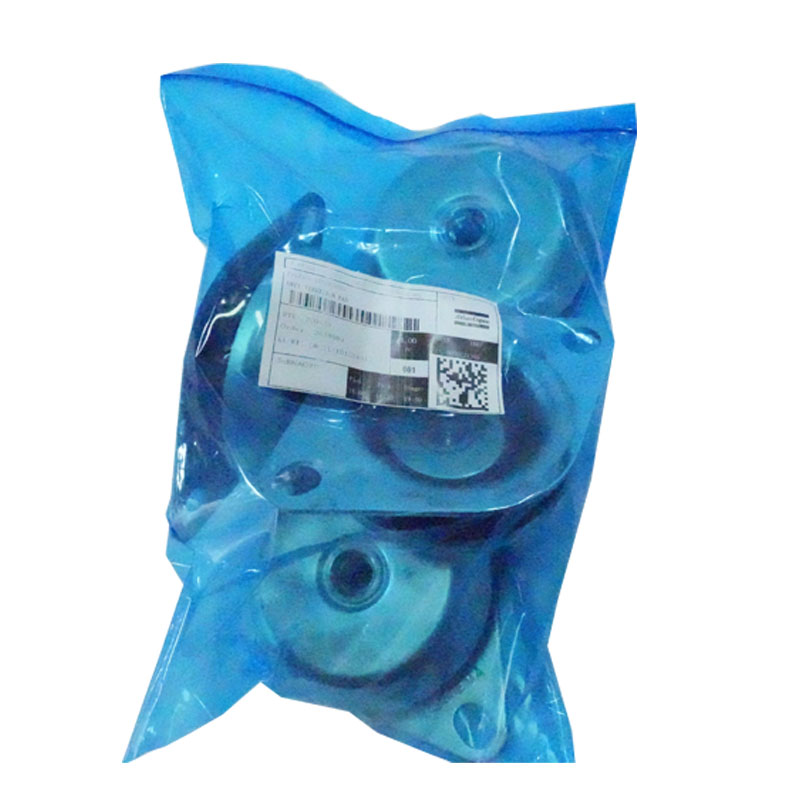
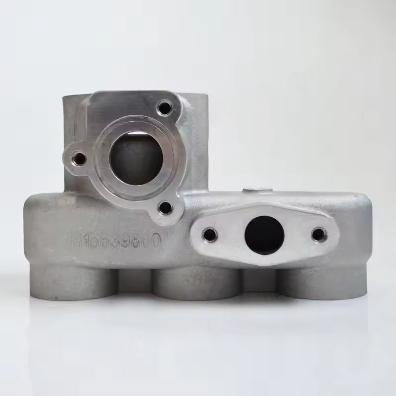
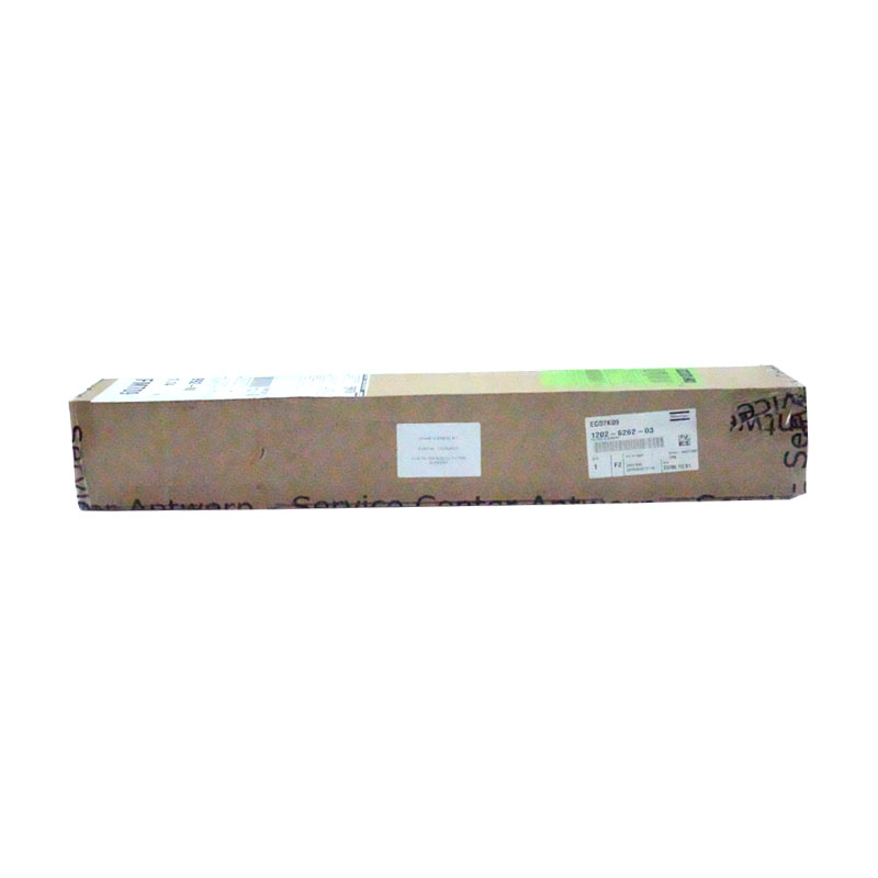
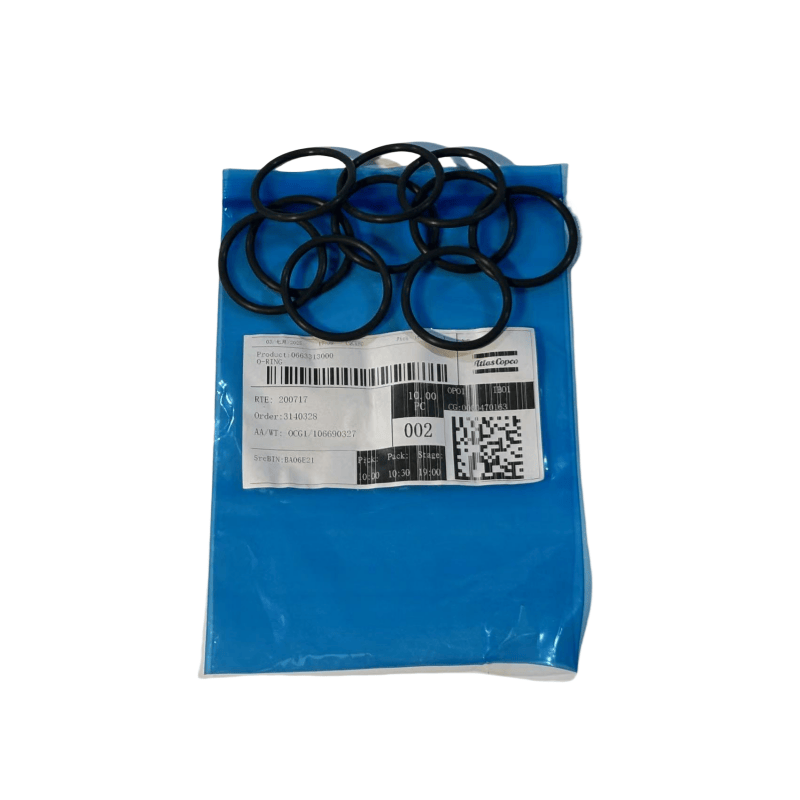
1619606800 Atlas Copco air Compressor DRAIN FOR OIL INJECTED SCREW COMPRESSOR
Atlas Copco's main functions
Power transmission: Transmits the power from the motor to the working components of the air compressor (such as the screw rotor, piston crankshaft), driving the compression mechanism to operate.
Speed regulation: Adjusts the rotational speed of the working components (such as lowering or increasing the rotor speed) through different gear combinations, matching the compression requirements.
Torque conversion: Changes the output torque of the power to ensure appropriate driving force in different working conditions (such as startup, full-load operation).
Synchronous operation: In double-screw air compressors (such as screw machines), gears ensure precise meshing and synchronous rotation of the male and female rotors, avoiding interference and collision.
Common types and applications
According to the type of air compressor and transmission requirements, it is mainly divided into the following categories:
Cylindrical gears
The teeth are distributed on the cylindrical surface, including straight teeth, helical teeth, and cross-shaped teeth, etc.
Application: Main transmission gears of screw-type air compressors (mostly helical gears, with smooth transmission and low noise), crankshaft gears of piston-type air compressors.
Characteristics: Simple structure, high transmission efficiency (up to 98% or more), suitable for parallel-axis transmission.
Conical gears
The teeth are distributed on the conical surface, used for transmission between intersecting axes (usually 90°).
Application: Transmission systems of some mobile air compressors, used when changing the direction of power transmission.
Characteristics: Can achieve vertical power transmission, but requires high manufacturing accuracy and is more expensive.
Synchronous gears
Designed specifically for double rotors (such as screw, sliding vane), ensuring that the two rotors maintain a fixed speed ratio and clearance.
Application: Air compressors without oil (as they do not rely on oil film lubrication, they need gear forced synchronization).
Characteristics: Extremely small tooth side clearance, high material strength, requires high-precision processing to ensure meshing accuracy.
Gear shaft
Integrated design of gears and shafts, suitable for small air compressors or low-load transmission.
Application: Transmission system of micro piston-type air compressors.
Key parameters and materials
Core parameters
Module (the basic parameter of gear size, determining the bearing capacity);
Number of teeth (affects the transmission ratio, the ratio of tooth count = inverse of rotational speed);
Tooth profile accuracy (usually 6-8 grades, the higher the accuracy, the lower the noise and longer the lifespan);
Contact strength and bending strength (resistance to tooth surface wear and fracture).
Common materials
Medium carbon alloy steel (such as 40Cr, 20CrMnTi): treated by carburizing and quenching, surface hardness high (HRC58-62), good toughness in the core, suitable for main transmission gears;
Cast iron (such as HT300): low cost, good wear resistance, suitable for low-load auxiliary gears;
Stainless steel: used in humid or corrosive environments to prevent rusting and affecting transmission.
Common faults and maintenance
Typical faults
Gear surface wear / pitting: caused by insufficient lubricating oil, poor oil quality or excessive impurities, manifested as pits and peeling on the gear surface.
Gear fracture: caused by overload operation, material defect or installation misalignment (such as parallelism deviation of the shaft), may be accompanied by severe abnormal noise.
Excessive tooth clearance: caused by long-term wear, will cause transmission shock, vibration and increased noise.
Adhesive damage: lubrication failure under high-speed heavy load, high-temperature adhesion of the gear surface causing metal peeling.
Maintenance points
Regular inspection: Observe the condition of the gear tooth surface, measure the tooth clearance, replace in time if abnormal.
Lubrication management: Use dedicated gear oil (or air compressor-specific oil), replace regularly and keep the oil level normal to avoid oil contamination.
Installation calibration: Ensure the parallelism and perpendicularity of the gear shaft meet the requirements, avoid unbalanced operation.
Load control: Prevent air compressors from operating under long-term overload, reduce fatigue damage to gears.
Design and maintenance of air compressor gears are crucial for the overall performance of the machine. High-precision gears with a good lubrication system can significantly reduce operating noise, extend service life, and ensure the efficient and stable operation of the air compressor.
Drainage device of the oil-injected screw compressor The drainage device of the oil-injected screw compressor (i.e., the oil-injected screw air compressor) is a key component for removing condensate water from the system. Its function is to prevent the mixture of water and lubricating oil, which could cause emulsification of the oil and reduce its lubrication effect, and to prevent water from entering the compressed air and affecting the equipment used for gas supply. Here is a detailed introduction to its drainage device:
The function and importance of the drainage device
Separating condensate water: During the cooling process of compressed air, condensate water is generated. The drainage device can promptly discharge this water from components such as the oil-gas separator, storage tank, cooler, etc.
Protecting lubricating oil: Preventing water from mixing into the lubricating oil, which could cause emulsification and deterioration of the oil, and avoiding poor lubrication that leads to wear of rotor, bearing, etc.
Ensuring gas quality: Reducing the moisture content in compressed air to meet the drying requirements of subsequent gas supply equipment (such as pneumatic tools, precision instruments).
Preventing corrosion: Avoiding the accumulation of water in pipelines and storage tanks, which could cause rust and shorten the lifespan of the equipment.
Common types and working principles
Based on the installation location and degree of automation, it is mainly divided into the following types:
Manual drainage valve
Structure: Simple ball valve or needle valve, installed at the bottom of the oil-gas separator, the lowest point of the storage tank, the drainage outlet of the cooler, etc.
Operation mode: Requires manual regular opening of the valve to discharge water, suitable for small air compressors or scenarios with low automation requirements.
Features: Low cost, simple structure, but requires manual operation. If the drainage is forgotten, it may lead to water accumulation.
Automatic drainage valve (float type)
Structure: Contains a float, lever, and sealed valve core, using the buoyancy of water to control the opening and closing of the valve.
Working principle: When the accumulated condensate water reaches a certain amount, the float rises, causing the valve core to open, and the water is discharged after which the float falls and closes the valve.
Application: Bottom of the oil-gas separator, storage tank, post-cooling, etc., can automatically discharge water without manual intervention.
Features: High reliability, suitable for medium and low-pressure systems, but requires regular cleaning of internal impurities to prevent jamming.
Electronic timed drainage valve
Structure: Composed of an electromagnetic valve, timer, and controller, which automatically opens for drainage by setting a drainage cycle (such as every 30 minutes) and drainage duration (such as 5 seconds).
Application: Compressed air pipelines, filters, dryers, etc., especially suitable for scenarios with fixed drainage frequency.
Features: Adjustable, adaptable to different conditions, but requires power supply, and may have accidental drainage (such as opening when there is no water).
Zero air loss drainage valve
Structure: Combines liquid level sensing and precise valve core, opening only when water is detected, with almost no loss of compressed air during drainage.
Working principle: Through electrodes or capacitive sensing of water level, the drainage channel is opened when there is water, and it closes immediately after the water is drained.
Application: Systems with energy consumption sensitivity, such as the oil-gas separator of large screw air compressors.
Features: Good energy efficiency, precise drainage, but higher cost. Installation
Installation location:
It should be installed at the lowest point of the equipment or pipeline (such as the bottom of the gas storage tank or the drainage outlet of the oil-gas separator), ensuring that the condensate water naturally converges.
The drainage outlet should be kept away from electrical components to prevent short circuits caused by splashing water during drainage.
For large systems, it is recommended to install drainage devices separately after multi-stage coolers and filters to improve drainage efficiency.
We use cookies to offer you a better browsing experience, analyze site traffic and personalize content. By using this site, you agree to our use of cookies.
Privacy Policy