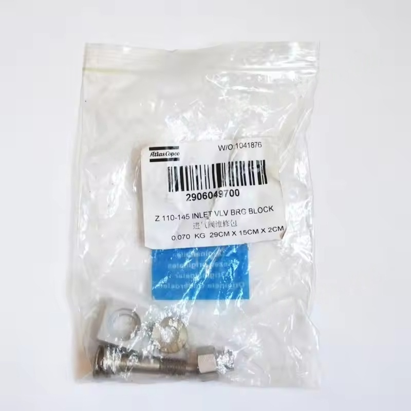
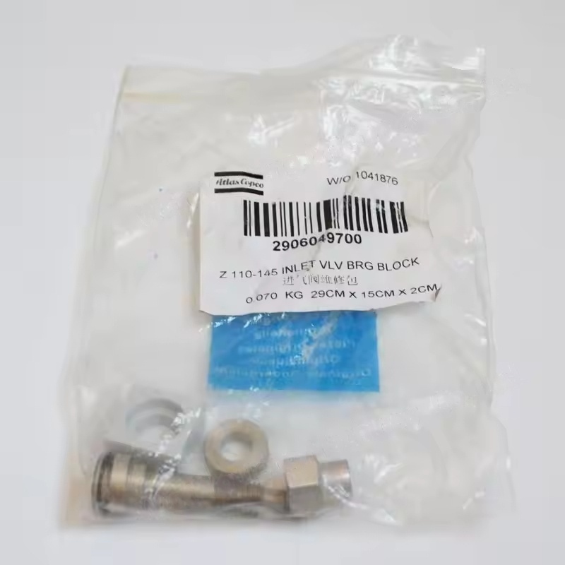
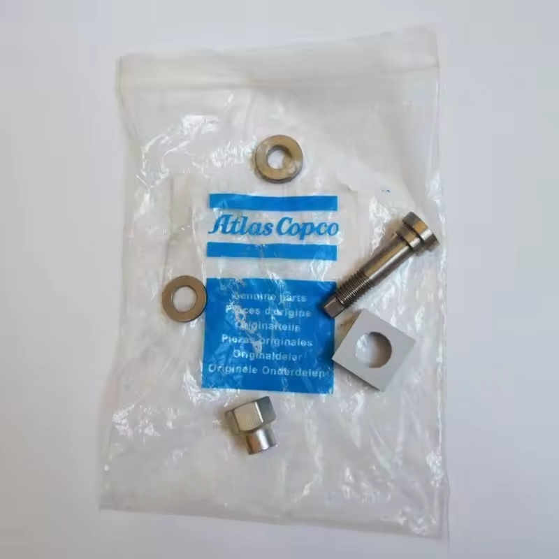
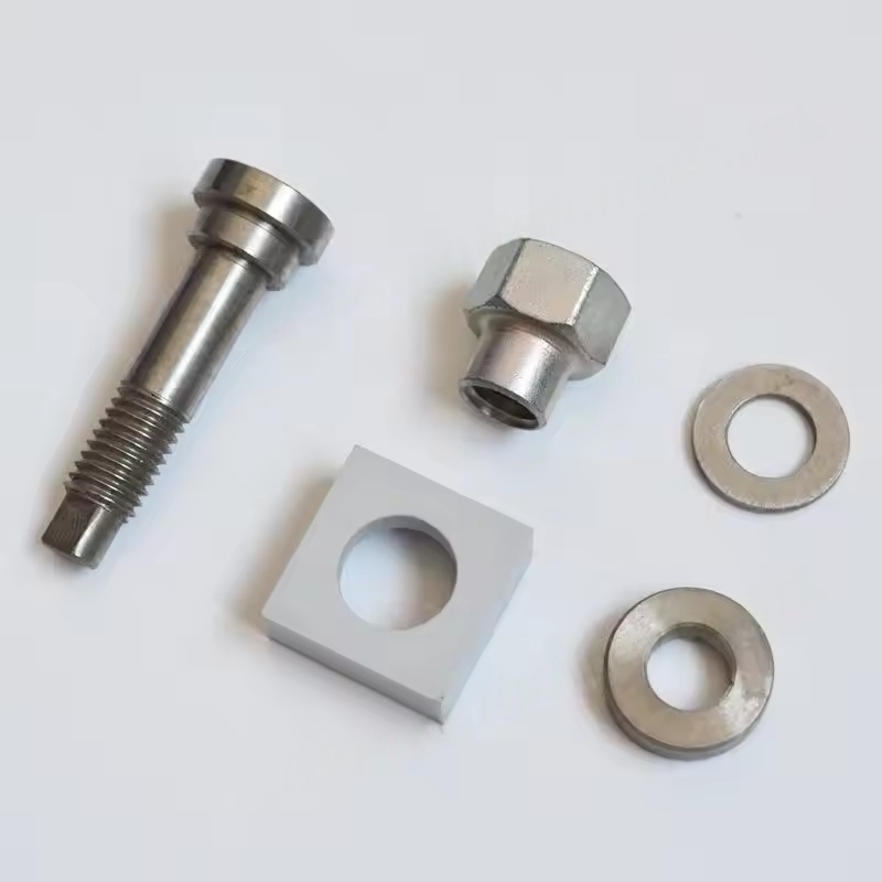
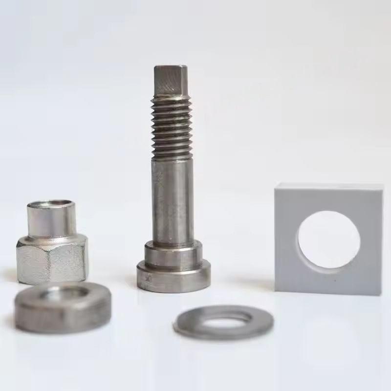
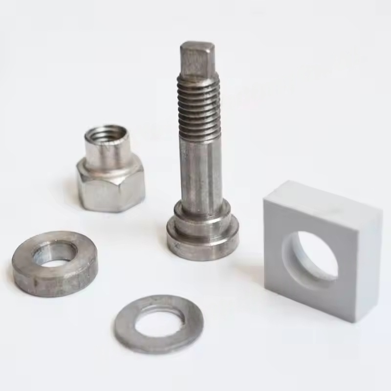
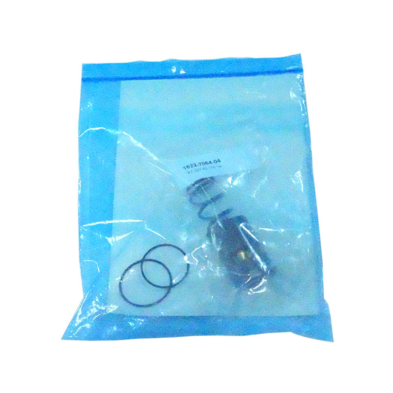
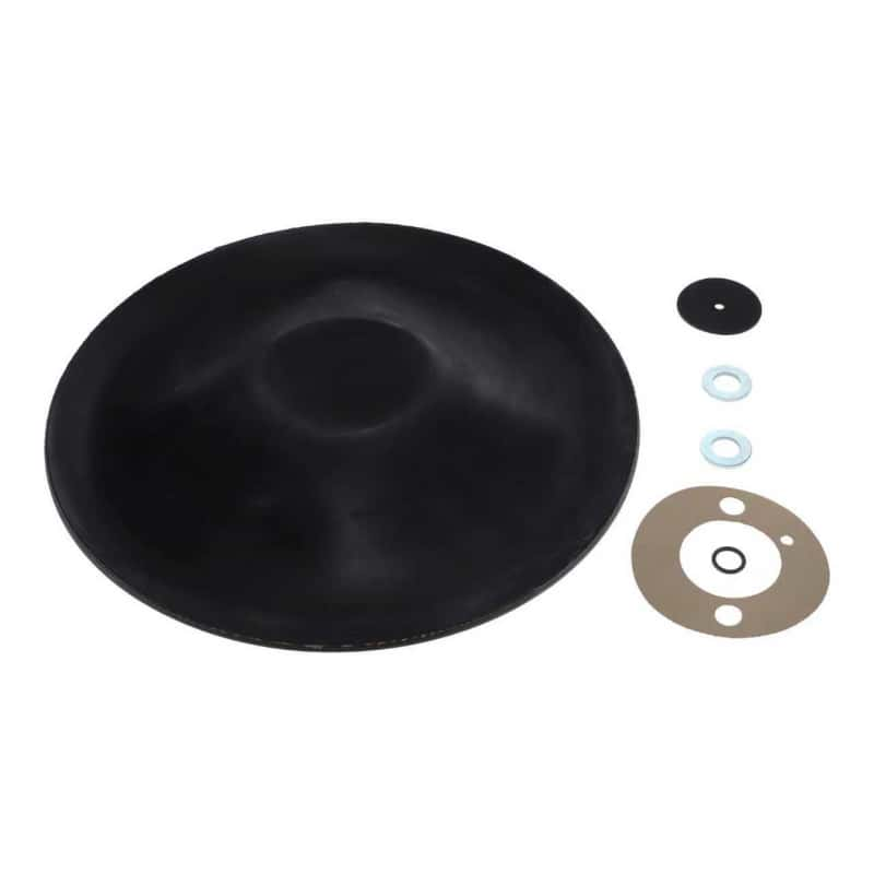
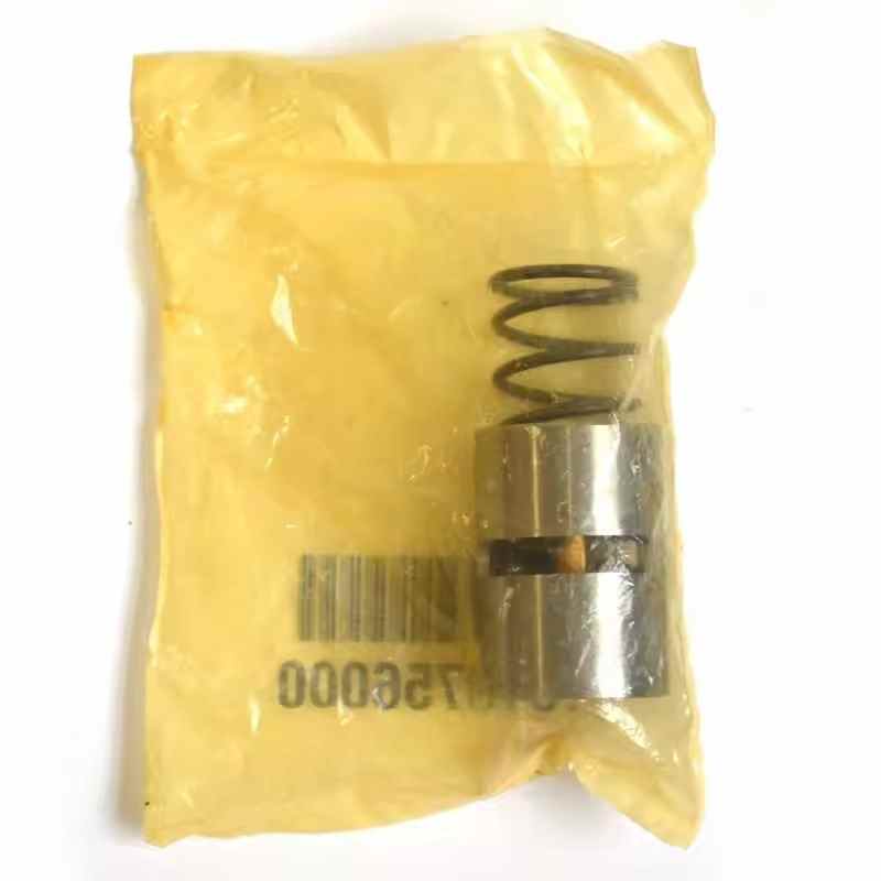
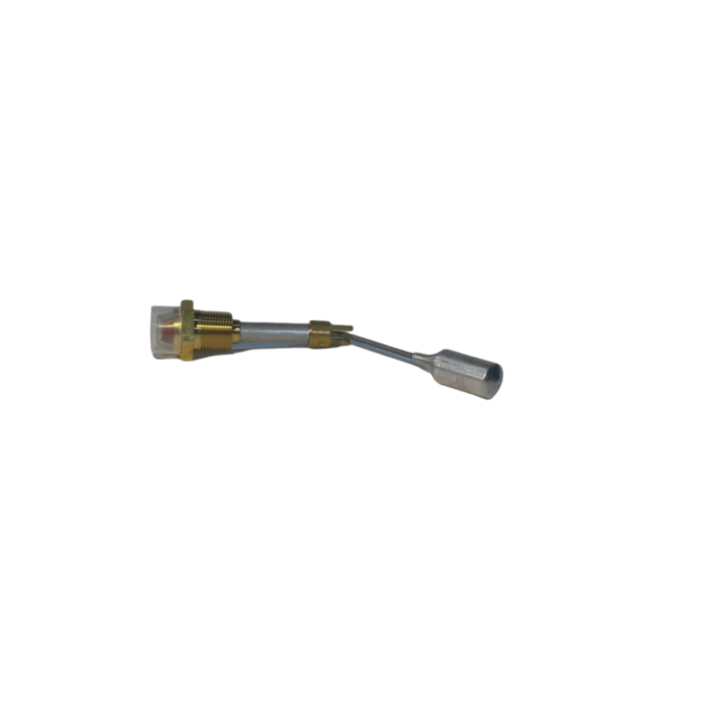
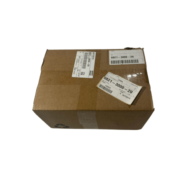
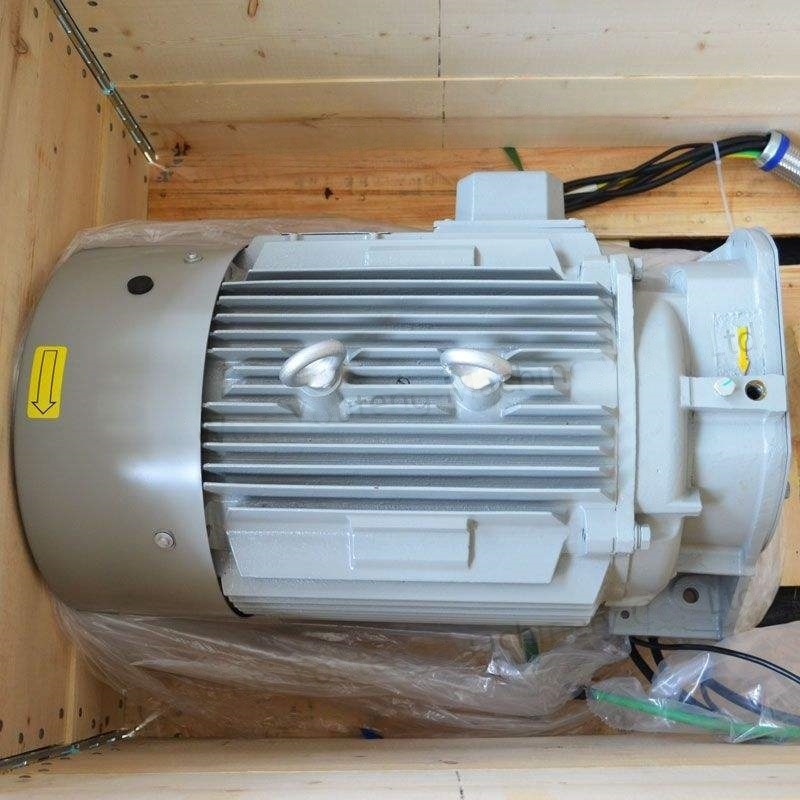
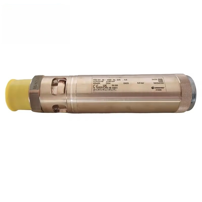
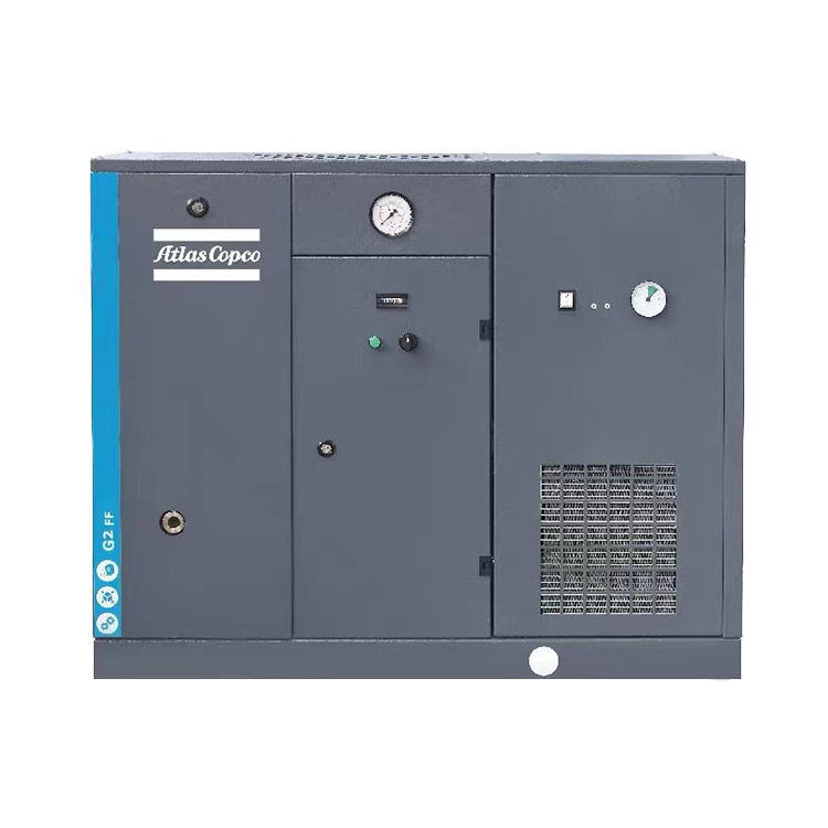
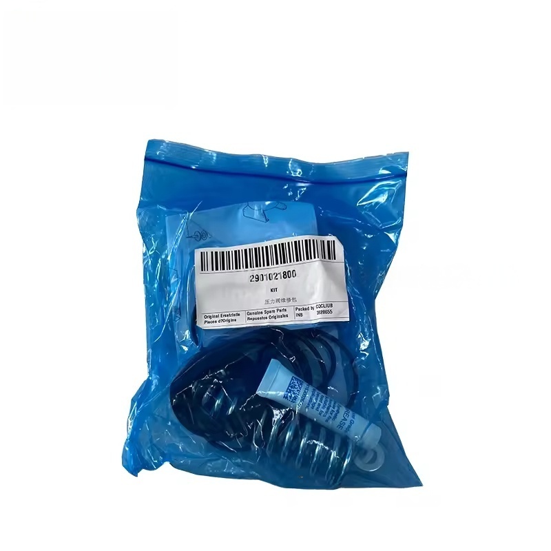
Atlas Copco Metal Screw Air Compressor Inlet Valve Kit Z110-145 INLET VLV BRG BLOCK 2906049700
Atlas Copco
I. Core Function of the Intake Valve Assembly
The Z110-145 intake valve assembly is a key component of the air compressor's intake system, primarily functioning as:
Controlling intake volume: Based on the system pressure requirements, the valve opening degree is adjusted to regulate the amount of air entering the main unit, enabling the compressor to operate at full load (full-load operation) or idle (energy-saving idling).
Ensuring sealing performance: When unloaded, the valve is fully closed to prevent compressed air from flowing back, reducing energy loss.
Protecting the main unit: In coordination with the regulator module, it achieves smooth loading and avoids sudden pressure shock that could damage components such as the rotor and bearings of the main unit.
The assembly typically includes a valve body, valve core, seals, springs, and check structures, and is designed to meet the pressure and flow requirements of the Z110-145 series models.
II. Function and Working Principle of the Intake Valve Regulator Module
The intake valve regulator module is the "control center" of the intake valve, driven by receiving signals from the control system (such as pressure sensor feedback), to operate the intake valve:
Signal processing: Receiving pressure signals from the air compressor system, determining whether to load or unload.
Drive control: Through electromagnetic directional valves or pneumatic components, controlling the opening / closing or opening/closing adjustment (such as proportional regulation) of the intake valve.
Status feedback: Some modules have feedback capabilities, transmitting the actual state of the intake valve to the main controller to ensure control accuracy.
Its working logic is: When the system pressure is below the set value, the regulator module drives the intake valve to open, enabling the air compressor to produce gas; when the pressure reaches the upper limit, the regulator module closes the intake valve, and the air compressor enters the unloaded state.
III. Common Faults and Their Effects
Intake Valve Assembly Faults
Valve core jamming: Due to oil contamination, impurities accumulation, or aging of the seals, the valve cannot fully open / close, resulting in insufficient gas production or rapid pressure drop during unloaded operation.
Poor sealing: Leakage when the valve is closed, causing increased energy consumption during unloaded operation and continuous idle operation of the main unit.
Spring failure: Leading to valve action stalling or abnormal opening/closing, affecting the stability of intake volume.
Regulator Module Faults
Electromagnetic directional valve failure: Unable to receive or execute control signals, causing the intake valve to fail to operate (always closed or open).
Pressure sensing anomaly: Module misjudges the system pressure, causing the air compressor to frequently load / unload, increasing energy consumption and mechanical wear.
Air path blockage: Blockage or leakage in the driving air path, resulting in slow or failure of the intake valve operation.
IV. Maintenance and Replacement Key Points Daily maintenance
Regularly (every 2000-4000 hours), inspect the cleanliness of the intake valve assembly, remove oil stains and impurities, and ensure that the valve core operates flexibly.
Check if the seals (such as O-rings, valve seats) are aged and replace them in time to ensure the sealing performance.
Inspect the electromagnetic valves and gas interface of the regulator module for leaks, ensuring the driving pressure is normal (usually 0.4-0.6 MPa).
Replacement precautions
It is necessary to select original factory components that match the Z110-145 series (such as the intake valve assembly number and regulator module number can be obtained through the equipment manual or official inquiries), ensuring compatibility in size and pressure parameters.
Before replacement, the machine needs to be shut down and depressurized to release the compressed air in the system, avoiding pressure operation.
After installation, it is necessary to conduct debugging: test whether the loading/unloading switching is smooth, and whether the pressure control is within the set range (such as loading pressure 0.7 MPa, unloading pressure 0.85 MPa, depending on the specific working conditions).
We use cookies to offer you a better browsing experience, analyze site traffic and personalize content. By using this site, you agree to our use of cookies.
Privacy Policy